Gen5 Storage Array Configuration
This guide provides the installation steps required for configuration of your LogRhythm Storage Array (LR-SA).
Audience
This guide is intended for systems engineers and other implementation specialists within LogRhythm Professional Services, who are LogRhythm Partners, or who are LogRhythm customers under the guidance of LogRhythm Professional Services.
Do not attempt to complete the steps in this guide without assistance from LogRhythm Support.
Prerequisites
The LR-SA is designed to increase the storage capacity of a LogRhythm High-Performance Appliance. The following configuration steps require taking the system offline to install new hardware.
- Before adding the LR-SA device, back up the LogRhythm Appliance. A minimum backup should include the SQL Server system databases (master, msdb, and model), the LogRhythmEMDB database, and all archived log files.
- If an antivirus scanner has been installed on the LogRhythm appliance, disable it. After the LR-SA has been added, make sure you enable the scanner again and update the exclusions to include the new data locations.
- Shut down the LogRhythm appliance. Be sure that the appliance and any attached devices, including any existing LR-SA storage devices, are powered off.
Hardware Overview
LogRhythm offers several storage arrays. Mounting rails, hardware, a RAID controller, and two SAS cables (2 meters in length) are included with each storage appliance.
Storage Array | Drive Specifications | Intended Use | RAID Controller and SAS Cables |
|---|---|---|---|
SAAR5120 | 24 x 12 TB 7,200 RPM SAS 2.5-inch | XM, DX, and DP appliances | PERC H840 RAID Controller with 8 GB Cache |
SAPM5020 | 24 x 900 GB 15,000 RPM SAS 2.5-inch 4 x 900 GB 15,000 RPM SAS 2.5-inch | PM appliances | PERC H840 RAID Controller with 8 GB Cache |
Configuration Overview
There are two supported RAID configurations for the LR-SA:
- Single-volume storage for archiving, indexing, and Network Monitor: 23-drive RAID 5 array with one drive configured as a hot spare
- Multi-volume storage for the Platform Manager: 18-drive RAID 10, four-drive RAID 10, and two-drive RAID 1 arrays
The following table lists the possible LR-SA configurations based on the LogRhythm High-Performance Appliance to which the storage array will be attached.
LogRhythm Appliance | Archive LR-SA | Indexed LR-SA | Maximum LR-SA |
|---|---|---|---|
LR-XM4500 Series | 1 | 1 | 1 |
LR-XM6500 Series | 1 | 1 | 1 |
LR-XM8500 Series | 1 | 1 | 1 |
LR-DP5500 Series | 1 | 0 | 1 |
LR-DP7500 Series | 1 | 0 | 1 |
LR-DX3500 Series | 0 | 2* | 2 |
LR-DX5500 Series | 0 | 2* | 2 |
LR-DX/DN7500 Series | 0 | 3* | 3 |
LR-PM5500 Series | 0 | 2 | 2 |
LR-PM7500 Series | 0 | 3 | 3 |
*For optimal indexing performance, LogRhythm recommends adding nodes instead of adding DAS.
A maximum of one LR-SA device can be added to an XM or DP5400/DP7400 Series appliance. A maximum of two LR‑SA devices can be added to 5500 Series appliances. A maximum of three LR-SA devices can be added to 7500 Series appliances. For example:
- The LR-XM6500 Series appliance can have a single LR-SA device attached, which can be configured either as archive storage or indexed storage.
- The LR-DX5500 Series appliance can have up to two LR-SA devices, both of which must be configured as indexed storage.
- The LR-PM7500 can have up to three LR-SA devices, all of which must be configured for indexed storage.
If multiple LR-SA devices will be installed at the same time, add them one at a time to avoid confusion about the drives.
Unpack and Rack the Storage Array
Unpack the array and identify each item, noted below. Keep all shipping materials in case they are needed later.
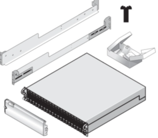
- Storage enclosure containing 24 SAS drives
- Rail kit (one pair of mounting rails and eight 10-32 x 0.5-inch flange-head Phillips screws)
- PERC H840 RAID Controller
- 2m SAS cables (2)
- Bezel
The storage array ships with a rack mount chassis and rails for mounting in a high-density server rack. Install the rails in a rack that meets the specifications of American National Standards Institute (ANSI)/Electronic Industries Association (EIA) standard ANSI/EIA-310-D-92, the International Electrotechnical Commission (IEC) 297, and Deutsche Industrie Norm (DIN) 41494.
For details about installation, refer to the Rack Installation guide that is included with your storage array rail kit.
Install the RAID Controller
Before the LogRhythm Appliance can use the LogRhythm Storage Array, you must install the included RAID controller in the LogRhythm Appliance.
- Shut down the LogRhythm Appliance and unplug both power supplies.
- Remove the lid of the LogRhythm Appliance by turning the lock on the black handle to unlock and then lifting up on the black handle.
- Depending on the model, there are between one and six PCIe slots available in the LogRhythm Appliance. The slots are located in the rear of the appliance.
- Insert the RAID controller in one of the available slots, making sure it is fully seated and locked in place.
- Replace the lid of the LogRhythm Appliance.
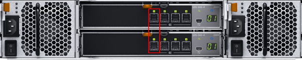
- Use the provided SAS cables to connect the ports on the RAID controller to the first port on each of the Enclosure Management Modules.
- Connect the power cables for the storage array, and then reconnect the power cables for the LogRhythm Appliance.
- Power on the storage array.
- Power on the LogRhythm Appliance.
Configure the Array
Before the LogRhythm Appliance will recognize the LogRhythm Storage Array, the newly installed RAID controller must be set up. It can be set up through RAID Controller BIOS Configuration Utility, iDRAC, or Dell OpenManage. This document illustrates configuration using the RAID Controller BIOS Configuration Utility method. For configuration using iDRAC or Dell OpenManage, please refer to vendor documentation.
Configure an Array for an XM, DP, or DX
For an XM, DP, or DX appliance, the array is configured as a single volume for maximum storage capacity. The 24 drives in the storage array will be configured as follows:
- Drives 0–22: RAID 5
- Drive 23: Hot spare
Configure Drives with the BIOS Configuration Utility
To configure the array using the BIOS-based configuration utility, do the following:
- Turn the system on. While the system is booting, the message Press <Ctrl><R> to Run Configuration Utility appears.
- Press Ctrl+R and wait for the configuration utility to load.
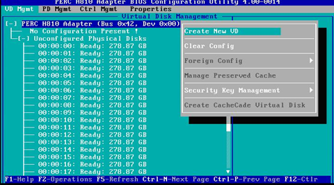
- After the utility loads, select the newly installed PERC adapter, and then press Enter.
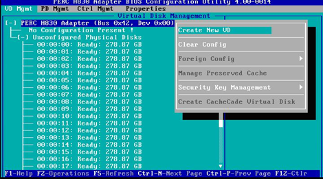
The Virtual Disk Management screen appears.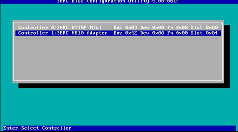
- With the top level selected, press F2, select Create New VD, and then press Enter.
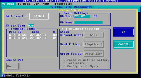
- For the RAID Level, select RAID-5.
- Select disks 0–22 in the Physical Disks section.
- Press Tab until OK is selected, and then press Enter.

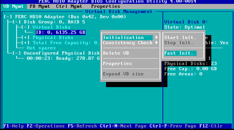
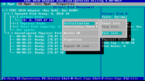
- To initialize the drive, select the new disk under Virtual Disks.
- Press F2, select Initialization, select Fast Init, and then press Enter.
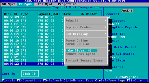
- After the drive is initialized, press Ctrl+N to move to the next page (Physical Disk Management).
- Select disk 23, press F2, select Make Global HS, and then press Enter.
- Press Esc to exit the configuration utility, and then press Ctrl+Alt+Del to reboot when prompted.
Windows Disk Configuration for an XM or DP
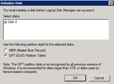
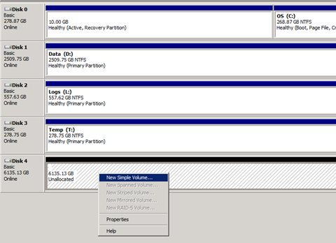
- Open the Windows Disk Management console through Server Manager, or type diskmgmt.msc in the search box.
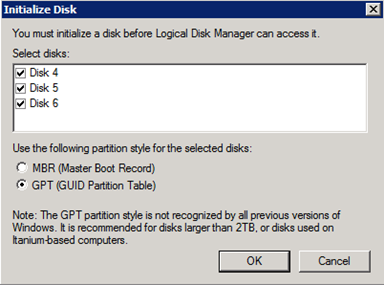
- Initialize the disk as GPT, and then click OK.
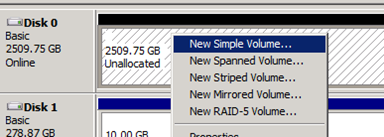
- Right-click the new disk, and then click New Simple Volume.
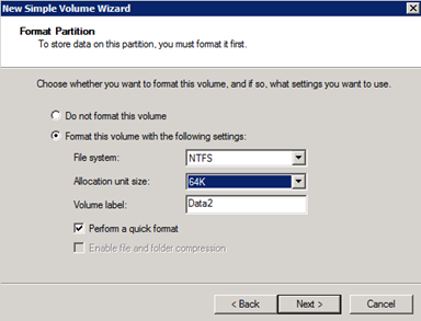
Choose a drive letter, provide a name, and then select the Perform a quick format check box.
E is recommended for an additional data drive and R is recommended for archive.
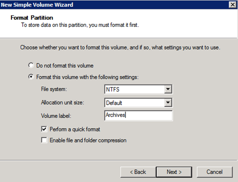
- Click Next.
Linux Disk Configuration for a DX
- Log in to the DX—either locally or via SSH—as logrhythm.
Type the following command to confirm that Linux recognizes the storage array:
CODEsudo fdisk –l /dev/sdcThe letter c in “/dev/sdc” represents the first array attached to a system. The second would be d (/dev/sdd), and the third would be e (/dev/sde).
Start the partitioning software:
CODEsudo parted /dev/sdcType the following commands to create a partition:
CODE$ mklabel gpt (parted) mkpart Partition name? []? Press Enter Filesystem type? [ext2]? Press Enter Start? 1 End? 26.4TB (parted) pr (parted) quitType the following command to make the file system on the new partition:
CODEsudo mkfs.ext4 –m 0 /dev/sdc1Make the directory to be used for the mount point for the new file system:
CODEsudo mkdir –p /usr/local/logrhythm/data/01If you have more than one array attached to the system, use increasing numbers for the directory under data. For example, the second array would be mounted on /.../data/02, and the third would be on /.../data/03.
- Add the newly created and configured file system and directory to the Linux file system table:
cd /etc
sudo vi fstab
- Press Shift+G, press Shift+A, and then press Enter.
Insert the following line:
CODE/dev/sdc1 /usr/local/logrhythm/data/01 ext4 nodev,noexec,nosuid,nofail 1 2Insert the following for the second and third array, if needed:
CODE/dev/sdd1 /usr/local/logrhythm/data/02 ext4 nodev,noexec,nosuid,nofail 1 2 /dev/sde1 /usr/local/logrhythm/data/03 ext4 nodev,noexec,nosuid,nofail 1 2
- Press Esc, type wq, and then press Enter.
- Confirm that the additional storage is mounted and available:
mount –a
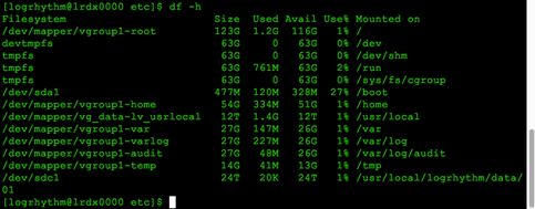
df –h
The output should look like the following: If more than one array is attached, you will see additional lines similar to the /dev/sdc1 line.
- Change the system owner of the new data directories:
sudo chown elasticsearch.elasticsearch /usr/local/logrhythm/data/
sudo chown elasticsearch.elasticsearch /usr/local/logrhythm/data/01
For a second or third array, use the following if needed:
CODEsudo chown elasticsearch.elasticsearch /usr/local/logrhythm/data/02 sudo chown elasticsearch.elasticsearch /usr/local/logrhythm/data/03
10. Confirm that the change was successful:
CODEls –alR /usr/local/logrhythm/data/
LogRhythm Archive Configuration
- In the Client Console, open the Deployment Manager.
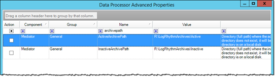
- Click the Data Processors tab, double-click the Data Processor on which you want to change the archive path, and then double-click Advanced.
- Change the ActiveArchivePath and InactiveArchivePath to the new drive.
- With the LogRhythm services stopped, copy the archives to the new location:
- Start > Run > cmd.exe
- Xcopy D:\LogRhythmArchives\*.* R:\LogRhythmArchives\ /s /h /e /o /k
- Start the LogRhythm services.
LogRhythm XM or DX Configuration in AllConf
Do not perform these steps until all systems in your cluster are configured properly. If they are not configured properly, your cluster will fail.
- Log in to AllConf on one of the DX nodes.
- Locate the path.data setting under Elasticsearch Server Settings.
Append the new path to the current setting using a comma (,) as the separator. For example, a DX with one array would have this as the setting:
CODE/usr/local/logrhythm/db/elasticsearch/data, /usr/local/logrhythm/data/01
An XM would have this as the setting:CODED:\LogRhythm\Data Indexer\Data\elasticsearch\data, E:\LogRhythm\Data Indexer\Data\elasticsearch\data- If using more than one array, append the specific data paths as needed.
- Click Submit at the bottom of the page.
You will be warned about changing the configuration. - Click Continue.
- Scroll right to see the change and verify the setting in the Value box.
Configure the Array for a PM
For a PM appliance, the array is configured for maximum performance. The 24 drives in the storage array are configured to extend database, log, and temp storage as follows:
- Drives 0–17: RAID 10
- Drives 18–21: RAID 10
- Drives 22–23: RAID 1
Configure Drives with the BIOS Configuration Utility
To configure the array using the BIOS-based configuration utility, do the following:
- Turn the system on. While the system is booting, the message Press <Ctrl><R> to Run Configuration Utility appears.
- Press Ctrl+R and wait for the configuration utility to load.
- After the utility loads, select the newly installed PERC adapter, and then press Enter.
The Virtual Disk Management screen appears.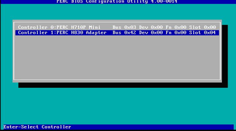
- With the top level selected, press F2, select Create New VD, and then press Enter.
- Select RAID-10 for the RAID Level.
- Enter 6 for PD per Span.
- Select disks 0–17 in the Physical Disks section.
- Press Tab until OK is selected, and then press Enter.

- To initialize the drive, select the new disk under Virtual Disks, press F2, select Initialization, select Fast Init, and then press Enter.
- Use the Up Arrow key to return to the top level, press F2, select Create New VD, and then press Enter.
- For the RAID level, select RAID-10.
- Set PD per Span to 2.
- Select disks 18–21 in the Physical Disks section.
- Press Tab until OK is selected, and then press Enter.

- To initialize the drive, select the newly created virtual disk, press F2, select Initialization, select Fast Init, and then press Enter.
- Use the Up Arrow key to return to the top level, press F2, select Create New VD, and then press Enter.
- Select RAID-1 for the RAID Level.
- Select disks 22 and 23 in the Physical Disks section.
- Press Tab until OK is selected, and then press Enter.
- To initialize the drive, select the newly created virtual disk, press F2, select Initialization, select Fast Init, and then press Enter. The fully configured array should look like this:
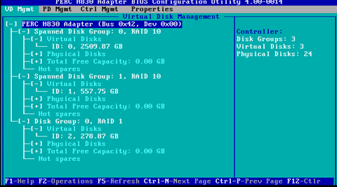
- Press Esc to exit the configuration utility, and then press Ctrl+Alt+Del to reboot when prompted.
Windows Disk Configuration
- Open the Windows Disk Management console through Server Manager, or type diskmgmt.msc in the search box.
- Initialize the disks as GPT, and then click OK.
- Locate the unallocated drive with a capacity of approximately 2,509 GB (note: the drive order will vary). Right-click the unallocated drive, and then click New Simple Volume.
- Select the appropriate drive letter. If this is the second data drive, select E; for the third, select F; and for the fourth, select G.
- Set the Allocation unit size to 64K, provide a descriptive name (Volume label), and then select the Perform a quick format check box.
- Repeat the previous steps 3–5 for these drives:
- Logs (approx. 557 GB, drive letter M, N, or O)
- Temp (approx. 278 GB, drive letter U, V, or W)
- Browse to the new data drive, and then create a new folder called LogRhythm.
- Browse to the new logs drive, and then create a new folder called LogRhythm.
- Browse to the new temp drive, and then create a new folder called Temp.
Expand the Databases to the New Storage
Now that the storage has been attached and mapped to drive letters, additional data files can be created with the following steps in order to extend the databases to the new storage location.
- Log in to SQL Server Management Studio, and then expand the Databases folder.
- For each LogRhythm Database:
- Right-click the database, and then click Properties.
- On the left-side navigation panel, click the Files page.
- Click Add.
- Provide a descriptive name (Logical Name) for the new data file. In this example, the second data file is being created for the LogMart database, so it is named “LogRhythm_LogMart2”.
- Set the Initial Size. LogRhythm recommends setting the Initial Size to match the size of the first data file. In this example, the Initial Size would be 394496 MB.
- Configure Autogrowth to match the first data file.
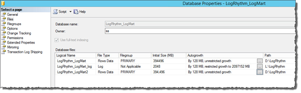
- Change the path to point to the LogRhythm directory on the data drive created in the previous step (E:\LogRhythm, F:\LogRhythm, or G:\LogRhythm).
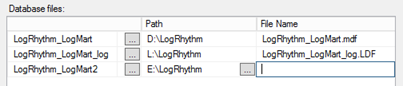
- The file name is created automatically. Click OK to save the change.
- Verify that the new file was created successfully by browsing to the file location.
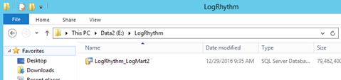
- Repeat these steps for each LogRhythm Database.
Expand TempDB to the New Storage
An additional data file must be added for TempDB.
- Log in to SQL Server Management Studio, expand the Databases folder, and then expand System Databases.
- Right-click tempdb, and then click Properties.
- Click the Files page on the left-side navigation panel.
- Click Add.
- Provide a descriptive name (Logical Name).
- Set the Initial Size. LogRhythm recommends setting the Initial Size to match the size of the first data file. In this example, the Initial Size would be 2048 MB.
- Configure Autogrowth to match the original tempdev file.
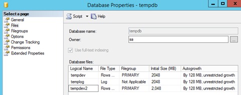
- Change the path to point to the Temp directory on the temp drive created in the previous step (U:\Temp, V:\Temp, or W:\Temp).
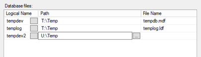
- The file name is created automatically. Click OK to save the change.
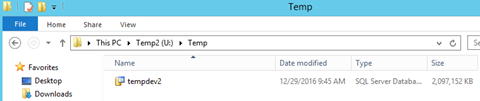
- Verify that the new file was created successfully by browsing to the file location.
Move the Log Files
Additional log files provide no benefit to SQL Server. Therefore, rather than adding new log files, the existing files will be moved in order to best take advantage of the space and performance of the additional disk.
- On a PM, a different log file will be moved for each LR-SA device that is added.
- For the first LR-SA device, the log file for the LogRhythm_LogMart database will be moved to the new logs drive (M:\LogRhythm).
- For the second LR-SA device, the log file for the LogRhythm_Events database will be moved to the new logs drive (N:\LogRhythm).
- For the third LR-SA device (LR-PM7450 only in this configuration), the log file for the LogRhythm_Alarms database will be moved to the new logs drive (O:\LogRhythm).
You must determine the Database Name, Logical Name, and Current Path for each LogRhythm database log file on the system. In the following example, the log file for LogRhythm_LogMart will be moved.
Make sure to substitute the correct names based on the recommendations above.
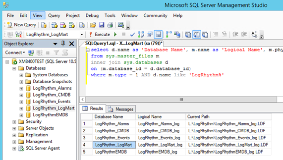
- Log in to SQL Server Management Studio, and then click New Query.
Copy the following query, paste it into the query window, and then click Execute.
CODEselect d.name as 'Database Name', m.name as 'Logical Name', m.physical_name as 'Current Path' from sys.master_files m inner join sys.databases d on (m.database_id = d.database_id) where m.type = 1 AND d.name like 'LogRhythm%'The necessary information appears for each log file.
The syntax for the move command is:CODEALTER DATABASE Database Name MODIFY FILE (NAME='Logical Name', FILENAME='New Path')For this example, where the LogRhythm_LogMart log file will be moved to the new M: drive, the command is:
CODEALTER DATABASE LogRhythm_LogMart MODIFY FILE (NAME='LogRhythm_LogMart_log', FILENAME='M:\LogRhythm\LogRhythm_LogMart_log.LDF')The following message will be displayed if the move is successful:

- Stop the SQL service and move the log file from the L: drive to the new location (in this example, M:).
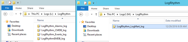
- Start the SQL service.
Appendix A: Drive Letter Reference
Drive Letters by Configuration
Storage Array | 1 x Index | 1 x Archive | 1 x Index | 2 x Index | 2 X Index | 3 x Index |
|---|---|---|---|---|---|---|
LR-XM4400 | C, D, E, L, T | C, D, L, R, T | - | - | - | - |
LR-PM5400 | C, D, E, L, M, T, U | - | - | C, D, E, F, L, M, N, T, U, V | - | - |
LR-XM6400 | C, D, E, L, T | C, D, L, R, T | - | - | - | - |
LR-PM7400 | C, D, E, L, M, T, U | - | - | C, D, E, F, L, M, N, T, U, V | - | C, D, E, F, G, L, M, N, O, T, U, V, W |
Appendix B: Configuration Options on PM Appliances
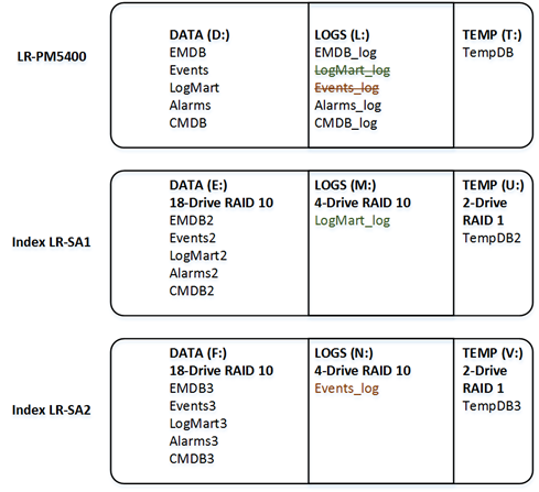
LR-PM5400
When an LR-SA is added to the PM5400, additional data files are created for each database on the E: drive, and also for TempDB on the U: drive. The LogMart log file is moved from the L: drive to the M: drive.
When a second LR-SA is added to the PM5400, additional data files are created for each database on the F: drive, and also for TempDB on the V: drive. The Events log file is moved from the L: drive to the N: drive.
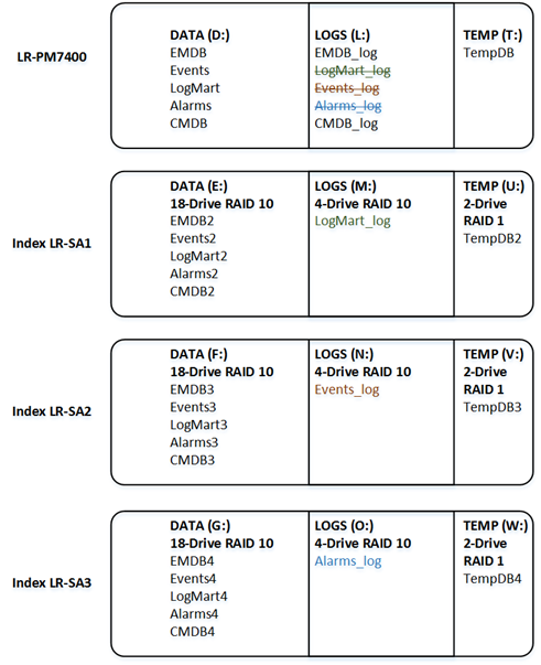
LR-PM7400
When an LR-SA is added to the PM7400, additional data files are created for each database on the E: drive, and also for TempDB on the U: drive. The LogMart log file is moved from the L: drive to the M: drive.
When a second LR-SA is added to the PM7400, additional data files are created for each database on the F: drive, and also for TempDB on the V: drive. The Events log file is moved from the L: drive to the N: drive.
When a third LR-SA is added to the PM7400, additional data files are created for each database on the G: drive, and also for TempDB on the W: drive. The Alarms log file is moved from the L: drive to the O: drive.